 | Common Criteria Evaluation and Validation SchemeNational Information
Assurance Partnership (NIAP) |
Title: Encrypting Retransmission Device (ERD)Maintained by: National Information Assurance Partnership (NIAP)Unique Identifier: 42Version: 1.5Status: draftDate of issue: 22 February 2024Approved by: Supersedes: Background and Purpose
This document describes a core set of security requirements for ERD.
These requirements cover basic security behavior for the ERD. Evaluation against
the resulting PP ensures that this fundamental set of requirements is met. These fundamental
requirements must be extended to adequately cover the functionality of many types of applications.
An ERD, in the context of this document, is a boundary device that has two functions,
encrypt traffic between two endpoints and convert traffic from one network media to
another network media while maintaining isolation from the less trusted network.
This is illustrated in Figure 1. The ERD must meet four security properties at the
boundary: confidentiality, isolation, separation, and authentication. These will be
referred to as “security”.
A more granular view of an ERD pair is in Figure 1b. An ERD consists of at least 2
physically separate computing units whose functionality is Encryption and Communication
respectively. They will be referred to as Encryption Unit (EU) and Communication Unit (CU).
An ERD is cryptographically bonded to another ERD and once bonded they are meant to only work
as a pair to create and manage a point-to-point encrypted tunnel between 2 trusted domains
over an untrusted domain as illustrated in Figure 2.
The EU and CU are independent. They must not share any hardware such as memory, cache, or other
internal infrastructure typical of computers. They must not run from a common software image.
Examples that meet this requirement might be a pair of SoC’s, each running an Operating System,
or a microProcessor and a microController, or an FPGA and a microProcessor. A pair of virtual
machines running on a single computer does not meet this separation requirement.
The CU interface at IC3 could be wireless (Bluetooth, WiFi, 5G, Microwave, etc.) or wired
media (ethernet, fiber, USB, serial, etc.) depending on specific use case. There is no restriction.
For example, where the Untrusted domain is an Ethernet:IP based network, the CU would need an RJ45
interface. That interface is then assigned an IP address and the destination IP address of its peer
CU is assigned to the function that transfers packets to and from the EU. The Untrusted domain (not the CU)
will handle the routing between ERD’s. The CU functions as a translation as well as a network interface device.
The IC1 and IC2 is always wired media.
The EU-to-EU association is a link layer (layer 2) tunnel and not a layer 3 or higher tunnel. However, a
layer 3 (or higher) tunnel can independently exist between CU-to-CU to transport the EU-to-EU frames.
The CU-to-CU tunnel is out of scope for this document.
The CU and EU must be managed independently from the untrusted and trusted domain respectively.
The isolation boundary of IC2 in Figure 2 (intentionally) prevents them from being managed from a common
location. Managing the CU from the trusted domain, either through the EU or around the EU is not in scope
of this document. The EU can be manually managed (from the trusted domain) or it can operate autonomously
depending on the use case requirements. Because the association is only between a pair of ERD’s, they can
successfully autonomously manage themselves if that is sufficient for a use case.
Use Cases
This technology has many specific use cases. The basic principle is to interject an encryption operation
network agnostically and transparently between 2 endpoints that already communicate without that encryption operation.
For example, a mobile phone with an ERD in a sleeve (the phone radio is disabled) and a remote enterprise VOIP service.
Or a satellite to a ground station. Or a Satellite-to-Satellite link. An IoT edge device (e.g. thermostat) to a server.
A substation to the main power station. Factory automation between controller and robot. A UAV to its controller or
UAV to UAV. A link between an automobile and the manufacturer for updates and telemetry. Isolation of a subsystem
within a system, e.g. separate the audio ECU from the engine ECU’s running on the automobile CAN bus. A branch office
to another branch office. The EUD in the trusted domain can be one or many devices. The ERD pair can also act as an
additional authentication mechanism since there is a unique cryptographic association. For example, a service technician
can be authenticated when doing remote maintenance merely by having one end of the ERD pair while the other end is at
the ingress point to the system being maintained.
However, in formal Common Criteria evaluations we seek evaluation only of solutions designed to: 1) replace commercial
networking capability internal to an End User Device (EUD) with an external device (e.g. Ethernet, LTE, Wi-Fi, etc.),
2) provide an encrypted tunnel to protect data in transit between EUD’s over said external interface.
Resources to be protected
- Sensitive data in transit
- Cryptographic key material to perform secure communications
- EU from unauthenticated access
Evaluation Boundary
Referencing Figure 2 above, the evaluation boundary consists of the hardware/software within the two ERD
modules (ERD 1 and ERD 1’) as well as the cryptographic link between the modules. More specifically, the
infrastructure to process data entering and leaving EU1 and EU1’ within the blue dashed box.
Essential Security Requirements
Functionality-related requirements are:
- At a minimum, the cryptography between ERD’s must be CNSA 2.0 compliant and use the Quantum Resistant key exchange finalists defined by NIST.
- The cryptography must employ anti-replay and integrity checking.
- The initial key to bond a pair of ERD’s can be pre-placed or input via a side channel at the time of provisioning.
- Once bonded/provisioned, the pair will manage the keys autonomously, with periodic rekey, recovery and zeroization upon an alarm or button event.
- Management of the EU must be careful to not introduce a new attack surface. The management actions anticipated are: start, stop, copy of log, and provision.
- The data pipeline between both sides of the Encryption Unit (EU) must be non-bypassable.
- The connectivity between the ERD and EUD must utilize wired technology.
- There must be a protocol break between CU and EU.
- The ERD pair must implement logging and audit capabilities. These must be authenticated activities, minimally with strong password.
The logs of the EU will be less verbose than logs of the CU given the very specific function of the EU vs. the complex activities
related to the untrusted network and the CU. This will limit the need to audit/log the EU in many cases.
- All the ERD interfaces that touch IC1 and IC2 in Figure 2 must be non-addressable.
- The frames that transit IC1 and IC2 are treated as stateless. The framing protocol does not require a subsequent frame to
complete a protocol state nor is the internal structure examined.
Assumptions
An attacker is assumed to attempt attacks from the following vantage points:
- The commercial/wireless network (e.g. directly attack the radio on the CU).
- The public network the ERD pairs are communicating through. They are the man in the middle.
- Monitor/analyze traffic between ERD pairs as well as monitor any signals to/from an ERD.
- Inject attack vectors through the public network or directly to the ERD untrusted domain interface.
- The attacker is assumed to be able to gain control of the CU.
- One ERD of a pair could be stolen or lost and subject to physical attack.
- The trusted domain could attack the EU.
Optional Extensions
- Encryption unit consists of 2 independent computing units to perform 2 layers of encryption.
- ERD has passive anti-tamper techniques applied to the package.
- ERD has active anti-tamper techniques applied to the package.
Objective Requirements
There is an additional interface between EU and EUDA that serves as a cryptographic association between the
ERD and the EUD such that if any other EUD than EUDA were to attach at IC1:a, then the EU would not function.
There is an interface to allow PIN entry to start/initialize the EU.
Outside the Scope of Evaluation
The following list contains items that are explicitly out-of-scope for
any evaluation against the product PP:
- Any network or device connected to interface ‘a’ of the EU (Figure 3)
- Any network or device connected to interface ‘d’ of the CU (Figure 3)
 Figure 1:
ERD in the overall network
Figure 1:
ERD in the overall network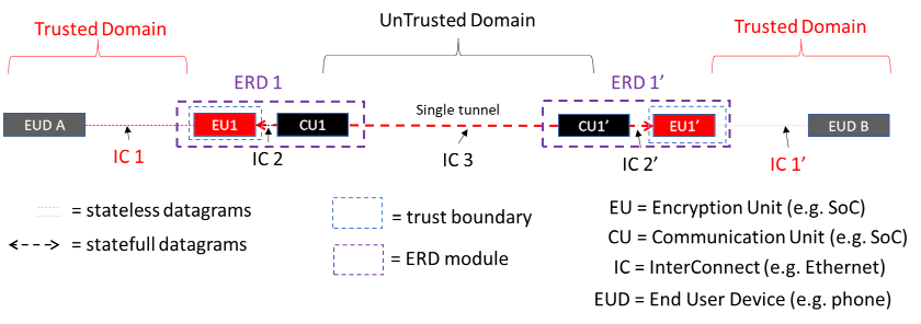 Figure 2:
ERD tunnel and domain separation view
Figure 2:
ERD tunnel and domain separation view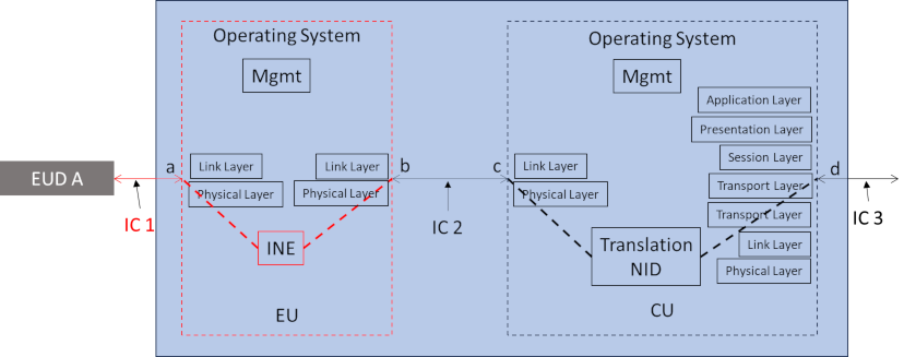 Figure 3:
ERD in a package
Figure 3:
ERD in a package