Protection Profile for Peripheral Sharing Devices

NIAP Logo
Version: 5.0
2025-07-11
National Information Assurance Partnership

Revision History

VersionDateComment
1.02000-08-08Initial Version
1.12007-07-25Update to conform with CC V3.1
1.22008-08-21Update to conform with additional parts of CC V3.1 r3
2.02010-06-01Updates to assumptions, threats, and objectives
2.12010-09-07Update to replace ROM requirement
3.02015-02-13Update to conform with CC V3.1 r4 and substantial additional functionality
4.02019-07-19Update to conform with CC V3.1 r5 and includes separation of security functionality into base Protection Profile and Protection Profile Modules based on interface type
5.02025-07-11First draft of version 1.0 for comment

Contents

1Introduction1.1Overview1.2Terms1.2.1Common Criteria Terms1.2.2Technical Terms1.3Compliant Targets of Evaluation1.3.1TOE Boundary1.3.1.1PSD Compliance Guidelines1.4Use Cases1.5Implementation-Based Features1.5.1Management1.5.2Automatic Tamper Response2Conformance Claims3Security Problem Definition3.1Threats3.2Assumptions3.3Organizational Security Policies4Security Objectives4.1Security Objectives for the Operational Environment4.2Security Objectives Rationale5Security Requirements5.1Security Functional Requirements5.1.1Auditable Events for Mandatory SFRs5.1.2Class FDP: User Data Protection5.1.3Class FPT: Protection of the TSF5.1.4TOE Security Functional Requirements Rationale5.2Security Assurance Requirements5.2.1Class ASE: Security Target5.2.2Class ADV: Development5.2.3Class AGD: Guidance Documentation5.2.4Class ALC: Life-cycle Support5.2.5Class ATE: Tests5.2.6Class AVA: Vulnerability AssessmentAppendix A - Optional RequirementsA.1Strictly Optional Requirements A.1.1 Auditable Events for Strictly Optional Requirements A.1.2Class ALC: Life-cycle SupportA.2Objective Requirements A.3Implementation-dependent Requirements A.3.1 Auditable Events for Implementation-dependent Requirements A.3.2Class FAU: Security AuditA.3.3Class FDP: User Data ProtectionA.3.4Class FIA: Identification and AuthenticationA.3.5Class FMT: Security ManagementA.3.6Class FPT: Protection of the TSFAppendix B - Selection-based Requirements B.1 Auditable Events for Selection-based Requirements B.2Class FDP: User Data ProtectionB.3Class FTA: TOE AccessAppendix C - Extended Component DefinitionsC.1Extended Components TableC.2Extended Component DefinitionsC.2.1Class FDP: User Data ProtectionC.2.1.1FDP_APC_EXT Active PSD ConnectionsC.2.1.2FDP_PDC_EXT Peripheral Device ConnectionC.2.1.3FDP_RIP_EXT Residual Information ProtectionC.2.1.4FDP_SWI_EXT PSD SwitchingC.2.2Class FPT: Protection of the TSFC.2.2.1FPT_FLS_EXT Failure with Preservation of Secure StateC.2.2.2FPT_NTA_EXT No Access to TOEC.2.2.3FPT_TST_EXT TSF TestingC.2.3Class FTA: TOE AccessC.2.3.1FTA_CIN_EXT Continuous IndicationsAppendix D - Isolation Documentation and AssessmentD.1GeneralD.2Design DescriptionD.3Isolation Means JustificationD.4Firmware DependenciesAppendix E - Peripheral Device ConnectionsE.1GeneralE.2Unauthorized Peripheral DevicesE.3Unauthorized Interface ProtocolsAppendix F - AcronymsAppendix G - Bibliography

1 Introduction

1.1 Overview

This Protection Profile (PP) describes common security requirements for Peripheral Sharing Devices (PSDs). A PSD is a device that provides a mechanism for securely connecting a set of peripherals to one or more attached computers. This Base‐PP may be used in conjunction with one or more PP‐Modules that describe the specific functional interfaces of that PSD type (i.e., audio, video, keyboard, user authentication device, or mouse), as described in section 2.

1.3 Compliant Targets of Evaluation

In the context of this PP, a PSD is an IT product for connecting one or more peripheral devices to one or more computers such that data cannot flow between computers by way of the peripherals or the PSD. Examples of PSDs that can claim compliance to this PP include Keyboard, Video, Mouse (KVM) switches; Keyboard, Mouse (KM) switches; and Isolators.

Examples of devices that cannot claim conformance to this PP include Extenders.

A PSD may be composed of one or more hardware components or platforms, and its software or firmware. It may include cables and accessories. PSDs that support more than one computer include a user interface that includes a visible indication of the selected computer interface and a mechanism for changing the selected computer interface. The user interface can be implemented on the chassis of the PSD using, for example, a touch screen or lights and buttons, or as part of a wired remote control.

An isolator or filter PSD is a device that provides the same security functions as a KVM but only to a single connected computer. Isolators do not require continuous display of the active interface.

1.3.1 TOE Boundary

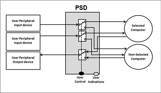
The TOE boundary is limited to the PSD itself. The TOE’s operational environment consists of one or more connected peripherals or computers. The typical usage of a multi‐computer PSD involves mapping interfaces between multiple computers such that the user is able to interact with the selected computers.

In this case, the TOE includes a user interface that allows a user to select the active computer. The user interface includes an indicator identifying the currently selected computer. Typical PSD usage is illustrated in Figure 1 below.

Figure 1: General TOE

1.3.1.1 PSD Compliance Guidelines

Connected peripheral devices, computer platforms, and connecting cables are not covered under this PP, but may be addressed by another PP. Nevertheless, testing of the TOE requires a complete setup that includes computers, cables, and peripheral devices.

PSDs covered by this PP: The following list includes additional characteristics that a conformant TOE must have or may have:

1.4 Use Cases

The following use cases are examples of PSDs covered by this PP.
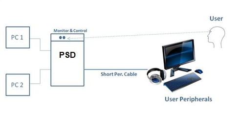
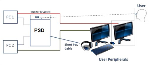
[USE CASE 1] Single User with PSD, Local Monitoring, and Local Control

Figure 2: Single User with PSD, Local Monitoring, and Local Control


In this use case, the user controls the PSD through a user interface on the PSD itself or through a directly connected remote controller. Peripheral devices are connected directly to the PSD using cables. Since the PSD resides in close physical proximity to the user, the user is expected to have physical access and full visibility of the PSD monitoring and control functions.

PSDs implementing this use case may support any type of supported peripheral as defined in this PP and its associated PP‐Modules.

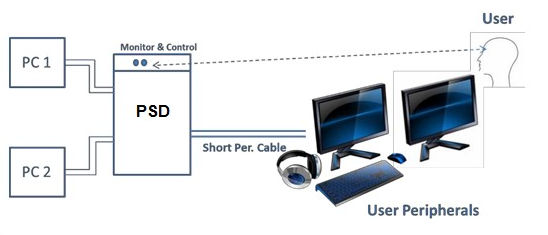
Note that the Operational Environment of this PSD may include peripherals that are connected directly to the connected computers (unconnected to the PSD) and multiple peripherals of the same type (for display or audio output only) each connected to the PSD, as shown in the figures below:

Figure 3: Single User with KM PSD and Peripherals Connected Directly to Computers


Figure 4: Single User with PSD and Multiple Peripherals of the Same Type
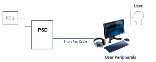
[USE CASE 2] Single User with PSD and a Single Computer (Isolator or Filter)

Figure 5: Single User with PSD and a Single Computer (Isolator or Filter)


In this use case, the PSD sits between a set of connected peripherals and a single connected computer. The connected computer may change over time, such as different laptops connected to an Isolator or Filter that persistently resides in a conference room. Once again, this use case does not specifically mandate or exclude the use of any one type of peripheral that is defined by this PP and its PP‐Modules.
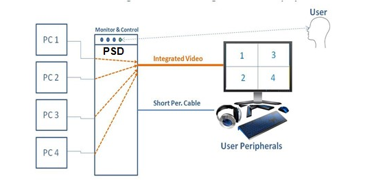
[USE CASE 3] PSD with Single Integrated Video Display (Combiner or Multi-Viewer)

Figure 6: PSD with Single Integrated Video Display (Combiner or Multi-Viewer)


A Combiner is used to simultaneously display output from multiple connected computers to one or more display devices. A Combiner PSD may combine the display output from multiple connected computers onto a single monitor (as shown in Figure 6 above) or output the display from one connected computer to be spanned onto multiple tiled or overlapping displays (e.g., a video wall). Any PSD TOE that claims to support this use case must have the ability to support display peripherals. Other supported peripherals can be claimed at the ST author’s discretion.
[USE CASE 4] [Invalid Use Case] Single User with PSD, Without Complete Local Monitoring or Local Control (Extender)
In this use case, the user controls the portion of PSD into which the peripherals are connected but is not necessarily in direct control of the entirety of the PSD or the connected computer. Since the full PSD does not necessarily reside in close physical proximity to the user, the user is not expected to have physical access and full visibility of the PSD monitoring and control functions.

1.5 Implementation-Based Features

A conformant TOE may implement certain features that are not strictly necessary in order to achieve the desired level of security, but if these features are implemented, it is expected that they conform to certain requirements governing their behavior.

1.5.1 Management

The TSF implements a management interface for its configuration. This generally exists when it is possible to configure the device filtration behavior of the TOE to explicitly allow or reject certain devices. When this functionality is implemented, it is expected that an interface exists that requires an authorized user to authenticate to the TOE, and that an audit log with reliable timestamps be generated to record the configuration activities performed against the TOE.

If this feature is implemented by the TOE, the following requirements must be claimed in the ST:

1.5.2 Automatic Tamper Response

The TSF implements an automatic tamper response mechanism that renders the TSF unusable when physical tampering has been detected.

If this feature is implemented by the TOE, the following requirements must be claimed in the ST:

2 Conformance Claims

Conformance Statement

An ST must claim exact conformance to this PP.

The evaluation methods used for evaluating the TOE are a combination of the workunits defined in [CEM] as well as the Evaluation Activities for ensuring that individual SFRs and SARs have a sufficient level of supporting evidence in the Security Target and guidance documentation and have been sufficiently tested by the laboratory as part of completing ATE_IND.1. Any functional packages this PP claims similarly contain their own Evaluation Activities that are used in this same manner.
CC Conformance Claims

This PP is conformant to Part 2 (extended) and Part 3 (conformant) of Common Criteria CC:2022, Revision 1.
PP Claim

This PP does not claim conformance to any Protection Profile.

The following PPs and PP-Modules are allowed to be specified in a PP-Configuration with this PP:
Package Claim

This PP is not conformant to any Functional or Assurance Packages.

3 Security Problem Definition

3.1 Threats

T.DATA_LEAK
A connection via the PSD between one or more computers may allow unauthorized data flow through the PSD or its connected peripherals.
T.FAILED
Detectable failure of a PSD may cause an unauthorized information flow or weakening of PSD security functions.
T.LOGICAL_TAMPER
An attached device (computer or peripheral) with malware, or otherwise under the control of a malicious user, could modify or overwrite code or data stored in the PSD’s volatile or non‐volatile memory to allow unauthorized information flows.
T.PHYSICAL_TAMPER
A malicious user or human agent could physically modify the PSD to allow unauthorized information flows.
T.REPLACEMENT
A malicious human agent could replace the PSD during shipping, storage, or use with an alternate device that does not enforce the PSD security policies.
T.RESIDUAL_LEAK
A PSD may leak (partial, residual, or echo) user data between the intended connected computer and another unintended connected computer.
T.SIGNAL_LEAK
A connection via the PSD between one or more computers may allow unauthorized data flow through bit‐by‐bit signaling.
T.UNAUTHORIZED_DEVICES
The use of an unauthorized peripheral device with a specific PSD peripheral port may allow unauthorized data flows between connected devices or enable an attack on the PSD or its connected computers.
T.UNINTENDED_USE
A PSD may connect the user to a computer other than the one to which the user intended to connect.

3.2 Assumptions

A.NO_TEMPEST
Computers and peripheral devices connected to the PSD are not TEMPEST approved.
A.NO_WIRELESS_DEVICES
The environment includes no wireless peripheral devices.
A.PHYSICAL
The environment provides physical security commensurate with the value of the TOE and the data it processes and contains.
A.TRUSTED_ADMIN
PSD administrators and users are trusted to follow and apply all guidance in a trusted manner.
A.TRUSTED_CONFIG
Personnel configuring the PSD and its operational environment follow the applicable security configuration guidance.
A.USER_ALLOWED_ACCESS
All PSD users are allowed to interact with all connected computers. It is not the role of the PSD to prevent or otherwise control user access to connected computers. Computers or their connected network shall have the required means to authenticate the user and to control access to their various resources.

3.3 Organizational Security Policies

This document does not define any additional OSPs.

4 Security Objectives

4.1 Security Objectives for the Operational Environment

The following subsections describe objectives for the operational environment.
OE.NO_TEMPEST
The operational environment will not use TEMPEST approved equipment.
OE.NO_WIRELESS_DEVICES
The operational environment will not include wireless keyboards, mice, audio, user authentication, or video devices.
OE.PHYSICAL
The operational environment will provide physical security, commensurate with the value of the PSD and the data that transits it.
OE.TRUSTED_ADMIN
The operational environment will ensure that trusted PSD Administrators and users are appropriately trained.
OE.TRUSTED_CONFIG
The operational environment will ensure that administrators configuring the PSD and its operational environment follow the applicable security configuration guidance.

4.2 Security Objectives Rationale

This section describes how the assumptions and organizational security policies map to operational environment security objectives.
Table 1: Security Objectives Rationale
Assumption or OSPSecurity ObjectivesRationale
A.NO_​TEMPESTOE.NO_​TEMPESTIf the TOE’s operational environment does not include TEMPEST approved equipment, then the assumption is satisfied.
A.NO_​WIRELESS_​DEVICESOE.NO_​WIRELESS_​DEVICESIf the TOE’s operational environment does not include wireless peripherals, then the assumption is satisfied.
A.PHYSICALOE.PHYSICALIf the TOE’s operational environment provides physical security, then the assumption is satisfied.
A.TRUSTED_​ADMINOE.TRUSTED_​ADMINIf the TOE’s operational environment ensures that only trusted administrators will manage the TSF, then the assumption is satisfied.
A.TRUSTED_​CONFIGOE.TRUSTED_​CONFIGIf TOE administrators follow the provided security configuration guidance, then the assumption is satisfied.
A.USER_​ALLOWED_​ACCESSOE.PHYSICALIf the TOE’s operational environment provides physical access to connected computers, then the assumption is satisfied.

5 Security Requirements

This chapter describes the security requirements which have to be fulfilled by the product under evaluation. Those requirements comprise functional components from Part 2 and assurance components from Part 3 of [CC]. The following conventions are used for the completion of operations:

5.1 Security Functional Requirements

5.1.1 Auditable Events for Mandatory SFRs

Table 2: Auditable Events for Mandatory Requirements
RequirementAuditable EventsAdditional Audit Record Contents
FDP_APC_EXT.1
No events specifiedN/A
FDP_PDC_EXT.1
Self-test failuresNone
FDP_RIP_EXT.1
No events specifiedN/A
FDP_SWI_EXT.1
No events specifiedN/A
FPT_FLS_EXT.1
No events specifiedN/A
FPT_NTA_EXT.1
No events specifiedN/A
FPT_PHP.1
Detection of intrusion.None
FPT_TST.1
Execution of the TSF self-testsResults of the tests
FPT_TST_EXT.1
Execution of self-tests. None.

5.1.2 Class FDP: User Data Protection

FDP_APC_EXT.1 Active PSD Connections

The TSF shall route user data only to or from the interfaces selected by the user.
The TSF shall ensure that no data flows between connected computers whether the TOE is powered on or powered off.
The TSF shall ensure that no data transits the TOE when the TOE is powered off.
The TSF shall ensure that no data transits the TOE when the TOE is in a failure state.
The evaluator shall verify that the TSS describes the conditions under which the TOE enters a failure state.
Guidance
The evaluator shall verify that the operational user guidance describes how a user knows when the TOE enters a failure state.
Isolation
The evaluator shall review the Isolation Documentation and Assessment as described in Appendix D of this PP and ensure that it adequately describes the isolation concepts and implementation in the TOE and why it can be relied upon to provide proper isolation between connected computers whether the TOE is powered on or powered off.
Tests
There are no test activities for this component.

FDP_PDC_EXT.1 Peripheral Device Connection

The TSF shall reject connections with unauthorized devices upon TOE power up and upon connection of a peripheral device to a powered‐on TOE.
The TSF shall reject connections with devices presenting unauthorized interface protocols upon TOE power up and upon connection of a peripheral device to a powered‐on TOE.
The TOE shall have no external interfaces other than those claimed by the TSF.
The TOE shall not have wireless interfaces.
The TOE shall provide a visual or auditory indication to the User when a peripheral is rejected.
Application Note: The list of unauthorized devices is in Appendix E: Peripheral Device Connections.

The TSF may elect to enforce rejection of unauthorized devices connected to the PSD through a USB hub by considering USB hubs as unauthorized devices.
The evaluator shall verify that the TSS describes the compatible devices for each peripheral port type supported by the TOE. The description must include sufficient detail to justify any PP‐Modules that extend this PP and are claimed by the TOE (e.g., if the ST claims the Audio Input PP‐Module, then the TSS shall reference one or more audio input devices as supported peripherals).

The evaluator shall verify that the TSS describes the interfaces between the PSD and computers and the PSD and peripherals, and ensure that the TOE does not contain wireless connections for these interfaces.

The evaluator shall verify that the list of peripheral devices and interfaces supported by the TOE does not include any prohibited peripheral devices or interface protocols specified in Appendix E.

The evaluator shall verify that the TSS describes all external physical interfaces implemented by the TOE, and that there are no external interfaces that are not claimed by the TSF.
Guidance
The evaluator shall verify that the operational user guidance provides clear direction for the connection of computers and peripheral devices to the TOE.

The evaluator shall verify that the operational user guidance provides clear direction for the usage and connection of TOE interfaces, including general information for computer, power, and peripheral devices.

The evaluator shall determine if interfaces that receive or transmit data to or from the TOE present a risk that these interfaces could be misused to import or export user data.

The evaluator shall verify that the operational user guidance describes the visual or auditory indications provided to a user when the TOE rejects the connection of a device.
Isolation
There are no Isolation evaluation activities for this component.
Tests
  • Test FDP_PDC_EXT.1:1: The evaluator shall check the TOE and its supplied cables and accessories to ensure that there are no external wired interfaces other than computer interfaces, peripheral device interfaces, and power interfaces.
  • Test FDP_PDC_EXT.1:2: The evaluator shall check the TOE for radio frequency certification information to ensure that the TOE does not support wireless interfaces.
  • Test FDP_PDC_EXT.1:3: The evaluator shall verify that the TOE ports properly reject unauthorized devices and devices with unauthorized protocols as per the Peripheral Device Connections (Appendix E).

    For this test, verify device rejection through TOE user indication in accordance with the operational user guidance, an immediate cessation of traffic following device detection or enumeration, or incompatibility of the device interface with the peripheral interface, and through no such device appearing in the real‐time hardware information console.
    1. Ensure the TOE is powered off. Open a real‐time hardware information console on the connected computer.
    2. Attempt to connect a USB mass storage device to the TOE peripheral interface.
    3. Power on the TOE. Verify the device is rejected.
    4. Ensure the USB mass storage device is disconnected, and then attempt to connect it to the TOE peripheral interface again.
    5. Verify the device is rejected.
    6. Power off the TOE. Connect an unauthorized USB device to a USB hub, and attempt to connect the USB hub to the TOE peripheral interface.
    7. Power on the TOE. Verify the device is rejected.
    8. Ensure the USB hub is disconnected, and then attempt to connect it to the TOE peripheral interface again.
    9. Verify the device is rejected.
    10. Power off the TOE. Attempt to connect any Personal System/2 (PS/2) device directly to the TOE peripheral interface.
    11. Power on the TOE. Verify the device is rejected.
    12. Ensure the PS/2 device is disconnected, and then attempt to connect it directly to the TOE peripheral interface again.
    13. Verify the device is rejected.

FDP_RIP_EXT.1 Residual Information Protection

The TSF shall ensure that no user data is written to TOE non‐volatile memory or storage.
The evaluator shall verify that the TSS includes a Letter of Volatility that provides the following information:
  • Which TOE components have non‐volatile memory, the non‐volatile memory technology, manufacturer/part number, and memory sizes;
  • Any data and data types that the TOE may store on each one of these components;
  • Whether or not each one of these parts is used to store user data and how this data may remain in the TOE after power down; and
  • Whether the specific component may be independently powered by something other than the TOE (e.g., by a connected computer).
Note that user configuration and TOE settings are not considered user data for purposes of this requirement.

The evaluator shall verify that the Letter of Volatility provides assurance that user data is not stored in TOE non‐volatile memory or storage.
Guidance
There are no additional Guidance evaluation activities for this component.
Isolation
There are no Isolation evaluation activities for this component.
Tests
There are no test activities for this component.

FDP_SWI_EXT.1 PSD Switching

The TSF shall ensure that [selection: the TOE supports only one connected computer, switching can be initiated only through express user action].
Application Note: If "switching can be initiated only through express user action" is selected, the ST must include the selection‐based requirements FDP_SWI_EXT.2 and FTA_CIN_EXT.1.
If the ST includes the selection the "TOE supports only one connected computer", the evaluator shall verify that the TSS indicates that the TOE supports only one connected computer.

If the ST includes the selection "switching can be initiated only through express user action", the evaluator shall verify that the TSS describes the TOE supported switching mechanisms and that those mechanisms can be initiated only through express user action.
Guidance
If the ST includes the selection "switching can be initiated only through express user action", the evaluator shall verify that the operational user guidance describes the TOE supported switching mechanisms.
Isolation
There are no Isolation evaluation activities for this component.
Tests
There are no test activities for this component.

5.1.3 Class FPT: Protection of the TSF

FPT_FLS_EXT.1 Failure with Preservation of Secure State

The TSF shall preserve a secure state when the following types of failures occur: failure of the power‐on self‐test and [selection: failure of the anti-tamper function, no other failures].
Application Note: In the context of this PP, a 'secure state' is defined by the TOE disabling all peripheral and connected computer interfaces when the correctness of its own functions cannot be assured.

Failure of the anti‐tamper function should be selected if FPT_PHP.3 is included in the ST.
This SFR is evaluated in conjunction with FPT_TST.1

FPT_NTA_EXT.1 No Access to TOE

TOE firmware, software, and memory shall not be accessible via the TOE’s external ports, with the following exceptions: [selection: the Extended Display Identification Data (EDID) memory of Video TOEs may be accessible from connected computers;, the configuration data, settings, and logging data that may be accessible by authorized administrators, no other exceptions]
The evaluator shall examine the TSS to ensure that the TSS documents that connected computers and peripherals do not have access to TOE software, firmware, and TOE memory, except as described above.
Guidance
The evaluator shall check the operational user guidance to ensure any configurations required to comply with this SFR are defined.
Isolation
There are no Isolation evaluation activities for this component.
Tests
There are no test activities for this component.

FPT_PHP.1 Passive Detection of Physical Attack

The TSF shall provide unambiguous detection of physical tampering that might compromise the TSF.
The TSF shall provide the capability to determine whether physical tampering with the TSF’s devices or TSF’s elements has occurred.
Application Note: FPT_PHP.1.1 include indications generated from application of optional SFR FPT_PHP.3
The evaluator shall verify that the TSS indicates that the TOE provides unambiguous detection of physical tampering of the TOE enclosure and TOE remote controller (if applicable). The evaluator shall verify that the TSS provides information that describes how the TOE indicates that it has been tampered with.
Guidance
The evaluator shall verify that the operational user guidance describes the mechanism by which the TOE provides unambiguous detection of physical tampering and provides the user with instructions for verifying that the TOE has not been tampered with.
Isolation
There are no Isolation evaluation activities for this component.
Tests
  • Test FPT_PHP.1:1: The evaluator shall verify, for each tamper evident seal or label affixed to the TOE enclosure and TOE remote controller (if applicable), that any attempts to open the enclosure or remove the seal results in the seal being damaged in a manner that is consistent with the operational user guidance.
  • Test FPT_PHP.1:2: The evaluator shall verify that it is not possible to administratively disable or otherwise prevent the display of any tampering indicators.

FPT_TST.1 TSF Testing

The TSF shall run a suite of the following self‐tests [during initial start‐up and at the conditions [selection: upon reset button activation, no other conditions]] to demonstrate the correct operation of [user control functions and [selection: active anti-tamper functionality, no other functions]].
The TSF shall provide authorized users with the capability to verify the integrity of [selection: [assignment: parts of TSF data], TSF data].
The TSF shall provide authorized users with the capability to verify the integrity of [selection: [assignment: parts of TSF], TSF].
Application Note: Reset button activation should be selected if the TOE includes such functionality.

If "active anti‐tamper functionality" is selected, portions of the evaluation activities will test functions from the optional active anti‐tamper SFR FPT_PHP.3.

Anyone with physical access to the TOE can be considered an authorized user.
The evaluator shall verify that the TSS describes the self‐ tests that are performed on start up or on reset (if "upon reset button activation" is selected). The evaluator shall verify that the self‐tests cover at least the following:
  • a test of the user interface – in particular, tests of the user control mechanism (e.g., checking that the front panel push‐buttons are not jammed) and
  • if "active anti‐tamper functionality" is selected, a test of any anti-tampering mechanism (e.g., checking that the backup battery is functional).
The evaluator shall verify that the TSS describes how the TOE ensures a shutdown upon a self‐test failure or a failed anti‐tampering function, if present. If there are instances when a shutdown does not occur (e.g., a failure is deemed non‐security relevant), those cases are identified and a rationale is provided explaining why the TOE’s ability to enforce its security policies is not affected.

The evaluator shall check the TSS to verify that it describes the TOE behavior in case of self‐test failure. The evaluator shall verify that the described TOE behavior includes shutting down the PSD functionality once the failure is detected.

The evaluator shall examine the TSS to verify that it describes how users verify the integrity of the selections in FPT_TST.1.2 and FPT_TST.1.3. This method can include restarting the TOE, a dedicated self‐test, or some other method.
Guidance
The evaluators shall verify that the operational user guidance describes how users verify the integrity of the selections in FPT_TST.1.2 and FPT_TST.1.3. This method can include restarting the TOE, a dedicated self‐test, or some other method.
Isolation
There are no Isolation evaluation activities for this component.
Tests
The evaluator shall trigger the conditions specified in the TSS that are used to initiate TSF self‐testing and verify that successful completion of the self-tests can be determined by following the corresponding steps in the operational guidance.

FPT_TST_EXT.1 TSF Testing

The TSF shall respond to a self‐test failure by providing users with a [selection: visual, auditory] indication of failure and by shutdown of normal TSF functions.
The evaluator shall check the TSS to verify that it describes the TOE behavior in case of self‐test failure. The evaluator shall verify that the described TOE behavior includes shutting down the PSD functionality once the failure is detected.
Guidance
The evaluator shall verify that the operational user guidance:
  • describes how the results of self-tests are indicated to the user
  • provides the user with a clear indication of how to recognize a failed self-test; and
  • details the appropriate actions to be completed in the event of a failed self-test.
The evaluator shall verify that the operational user guidance provides adequate information on TOE self-test failures, their causes, and their indications.
Isolation
There are no Isolation evaluation activities for this component.
Tests
The evaluator shall cause a TOE self-test failure and verify that the TOE responds by disabling normal functions and provides proper indications to the user.

5.1.4 TOE Security Functional Requirements Rationale

The following rationale provides justification for each SFR for the TOE, showing that the SFRs are suitable to address the specified threats:

Table 3: SFR Rationale
ThreatAddressed byRationale
T.DATA_​LEAKFDP_APC_EXT.1Mitigates this SFR by preventing unauthorized data flow.
FDP_PDC_EXT.1Mitigates this SFR by rejecting connection with unauthorized devices, including external and wireless interfaces.
T.FAILEDFPT_FLS_EXT.1Mitigates this SFR by preserving a secure state during failures.
FPT_TST.1Mitigates this SFR by running self-tests to verify integrity.
FPT_TST_EXT.1Mitigates this SFR by providing indication of a failure and shutting down normal functions.
T.LOGICAL_​TAMPERFPT_NTA_EXT.1Mitigates this SFR by preventing access to firmware, software, and memory except under specified exceptions.
T.PHYSICAL_​TAMPERFPT_PHP.1Mitigates this SFR by requiring detection of physical tampering.
FPT_PHP.3 (implementation-dependent)Mitigates this SFR by permanently disabling during a physical attack.
T.REPLACEMENTFPT_PHP.1Mitigates this SFR by ensuring physical tampering does not occur.
T.RESIDUAL_​LEAKFDP_RIP_EXT.1Mitigates this SFR by ensuring not data is transferred to non-volatile memory or storage.
FDP_RIP_EXT.2 (implementation-dependent)Mitigates this SFR by ensuring there is a purge memory to restore to the factory default functions.
T.SIGNAL_​LEAKFDP_APC_EXT.1Mitigates this SFR by ensuring data is only transferred to user-selected interfaces.
FDP_PDC_EXT.1Mitigates this SFR by rejecting unauthorized connections.
FDP_SWI_EXT.1Mitigates this SFR by ensuring there is only one connected computer unless a switch is authorized by user action.
FDP_SWI_EXT.2 (selection-based)Mitigates this SFR by ensuring only authorized users are able to initiate a switch.
T.UNAUTHORIZED_​DEVICESFDP_PDC_EXT.1Mitigates this SFR by rejecting connections with unauthorized devices.
T.UNINTENDED_​USEFDP_SWI_EXT.1Mitigates this SFR by ensuring there is only one connected computer unless a switch is authorized by user action.
FDP_SWI_EXT.2 (selection-based)Mitigates this SFR by ensuring only authorized users are able to initiate a switch.
FTA_CIN_EXT.1 (selection-based)Mitigates this SFR by requiring a visible indicator or the connection status.
FAU_GEN.1 (implementation-dependent)Mitigates this SFR by requiring the collection of audit data and peripheral device acceptance and rejection.
FIA_UAU.2 (implementation-dependent)Mitigates this SFR by requiring administrator-authentication.
FIA_UID.2 (implementation-dependent)Mitigates this SFR by requiring administrator-identification.
FMT_MOF.1 (implementation-dependent)Mitigates this SFR by restricting behavior modification of specified instructions to only the authorized administrator.
FMT_SMF.1 (implementation-dependent)Mitigates this SFR by requiring a list of management functions for the TSF.
FMT_SMR.1 (implementation-dependent)Mitigates this SFR by maintaining and associating roles, including administrators and users.
FPT_STM.1 (implementation-dependent)Mitigates this SFR by requiring reliable time stamp use.

5.2 Security Assurance Requirements

The Security Objectives for the TOE in Section 4.1 were constructed to address threats identified in Section 3.1. The Security Functional Requirements (SFRs) in Section 5.1 are a formal instantiation of the Security Objectives. The SARs were chosen based on the complexity of the products that are anticipated to be evaluated against this PP as well as the expected level of sophistication and access that an attacker would have if the TOE is deployed in an environment that satisfies the environmental security objectives in this PP.

This section lists the set of SARs drawn from CC Part 3 that are required in evaluations against this PP. Individual Evaluation Activities to be performed are specified both in Section 5.1 as well as in this section.

The general model for evaluation of TOEs against STs written to conform to this PP is as follows:

After the ST has been approved for evaluation, the Common Criteria Testing Laboratory (CCTL) will obtain the TOE, supporting IT environmental, and the administrative/user guides for the TOE. The CCTL is expected to perform actions mandated by the Common Evaluation Methodology (CEM) for the ASE and ALC SARs. The CCTL also performs the Evaluation Activities contained within Section 5.1, which are intended to be an interpretation of the other CEM assurance requirements as they apply to the specific technology instantiated in the TOE. The Evaluation Activities that are captured in Section 5.1 also provide clarification as to what the developer needs to provide to demonstrate the TOE is compliant with the PP.

The TOE security assurance requirements are identified in Table 4.

Table 4: Security Assurance Requirements

Assurance Class Assurance Components
Security Target (ST) (ASE) Conformance Claims (ASE_CCL.1)

Extended Components Definition (ASE_ECD.1)

ST Introduction (ASE_INT.1)

Security Objectives (ASE_OBJ.2)

Derived Security Requirements (ASE_REQ.2)

Security Problem Definition (ASE_SPD.1)

TOE Summary Specification (ASE_TSS.1)

Development (ADV) Basic Functional Specification (ADV_FSP.1)
Guidance Documents (AGD) Operational User Guidance (AGD_OPE.1)

Preparative Procedures (AGD_PRE.1)
Life-Cycle Support (ALC) Labeling of the TOE (ALC_CMC.1)

TOE CM Coverage (ALC_CMS.1)
Tests (ATE) Independent Testing - Conformance (ATE_IND.1)
Vulnerability Assessment (AVA) Vulnerability Survey (AVA_VAN.1)

5.2.1 Class ASE: Security Target

As per ASE activities defined in [CEM].

5.2.2 Class ADV: Development

The information about the TOE is contained in the guidance documentation available to the end user as well as the TSS portion of the ST. The TOE developer must concur with the description of the product that is contained in the TSS as it relates to the functional requirements. The Assurance Activities contained in should provide the ST authors with sufficient information to determine the appropriate content for the TSS section.

ADV_FSP.1 Basic Functional Specification (ADV_FSP.1)

The functional specification describes the Target Security Functions Interfaces (TSFIs). It is not necessary to have a formal or complete specification of these interfaces. Additionally, because TOEs conforming to this PP will necessarily have interfaces to the Operational Environment that are not directly able to be invoked by TOE users, there is little point specifying that such interfaces be described in and of themselves since only indirect testing of such interfaces may be possible. For this PP, the activities for this family should focus on understanding the interfaces presented in the TSS in response to the functional requirements and the interfaces presented in the AGD documentation. No additional "functional specification" documentation is necessary to satisfy the Evaluation Activities specified.

The interfaces that need to be evaluated are characterized through the information needed to perform the Evaluation Activities listed, rather than as an independent, abstract list.

Developer action elements:

The developer shall provide a functional specification.
The developer shall provide a tracing from the functional specification to the SFRs.
Application Note: As indicated in the introduction to this section, the functional specification is comprised of the information contained in the AGD_OPE and AGD_PRE documentation. The developer may reference a website accessible to application developers and the evaluator. The assurance activities in the functional requirements point to evidence that should exist in the documentation and TSS section; since these are directly associated with the SFRs, the tracing in element ADV_FSP.1.2D is implicitly already done and no additional documentation is necessary.

Content and presentation elements:

The functional specification shall describe the purpose and method of use for each SFR-enforcing and SFR-supporting TSFI.
The functional specification shall identify all parameters associated with each SFR-enforcing and SFR-supporting TSFI.
The functional specification shall provide rationale for the implicit categorization of interfaces as SFR-non-interfering.
The tracing shall demonstrate that the SFRs trace to TSFIs in the functional specification.

Evaluator action elements:

The evaluator shall confirm that the information provided meets all requirements for content and presentation of evidence.
The evaluator shall determine that the functional specification is an accurate and complete instantiation of the SFRs.
There are no specific assurance activities associated with these SARs, except ensuring the information is provided. The functional specification documentation is provided to support the evaluation activities described in , and other activities described for AGD, ATE, and AVA SARs. The requirements on the content of the functional specification information is implicitly assessed by virtue of the other assurance activities being performed; if the evaluator is unable to perform an activity because there is insufficient interface information, then an adequate functional specification has not been provided.

5.2.3 Class AGD: Guidance Documentation

The guidance documents will be provided with the ST. Guidance must include a description of how the IT personnel verifies that the Operational Environment can fulfill its role for the security functionality. The documentation should be in an informal style and readable by the IT personnel. Guidance must be provided for every operational environment that the product supports as claimed in the ST. This guidance includes instructions to successfully install the TSF in that environment; and Instructions to manage the security of the TSF as a product and as a component of the larger operational environment. Guidance pertaining to particular security functionality is also provided; requirements on such guidance are contained in the assurance activities specified with each requirement.

AGD_OPE.1 Operational User Guidance (AGD_OPE.1)

Developer action elements:

The developer shall provide operational user guidance.
Application Note: The operational user guidance does not have to be contained in a single document. Guidance to users, administrators and application developers can be spread among documents or web pages.

Rather than repeat information here, the developer should review the assurance activities for this component to ascertain the specifics of the guidance that the evaluator shall be checking for. This will provide the necessary information for the preparation of acceptable guidance.

Content and presentation elements:

The operational user guidance shall describe, for each user role, the user-accessible functions and privileges that should be controlled in a secure processing environment, including appropriate warnings.
Application Note: User and administrator are to be considered in the definition of user role.
The operational user guidance shall describe, for each user role, how to use the available interfaces provided by the TOE in a secure manner.
The operational user guidance shall describe, for each user role, the available functions and interfaces, in particular all security parameters under the control of the user, indicating secure values as appropriate.
Application Note: This portion of the operational user guidance should be presented in the form of a checklist that can be quickly executed by IT personnel (or end-users, when necessary) and suitable for use in compliance activities.

When possible, this guidance is to be expressed in the eXtensible Configuration Checklist Description Format (XCCDF) to support security automation.

Minimally, it should be presented in a structured format which includes a title for each configuration item, instructions for achieving the secure configuration, and any relevant rationale.
The operational user guidance shall, for each user role, clearly present each type of security-relevant event relative to the user-accessible functions that need to be performed, including changing the security characteristics of entities under the control of the TSF.
The operational user guidance shall identify all possible modes of operation of the TOE (including operation following failure or operational error), their consequences, and implications for maintaining secure operation.
The operational user guidance shall, for each user role, describe the security measures to be followed in order to fulfill the security objectives for the operational environment as described in the ST.
The operational user guidance shall be clear and reasonable.

Evaluator action elements:

The evaluator shall confirm that the information provided meets all requirements for content and presentation of evidence.
Some of the contents of the operational guidance are verified by the assurance activities in and evaluation of the TOE according to the [CEM]. The following additional information is also required. If cryptographic functions are provided by the TOE, the operational guidance shall contain instructions for configuring the cryptographic engine associated with the evaluated configuration of the TOE. It shall provide a warning to the administrator that use of other cryptographic engines was not evaluated nor tested during the CC evaluation of the TOE. The documentation must describe the process for verifying updates to the TOE by verifying a digital signature – this may be done by the TOE or the underlying platform. The evaluator shall verify that this process includes the following steps: Instructions for obtaining the update itself. This should include instructions for making the update accessible to the TOE (e.g., placement in a specific directory). Instructions for initiating the update process, as well as discerning whether the process was successful or unsuccessful. This includes generation of the hash or digital signature. The TOE will likely contain security functionality that does not fall in the scope of evaluation under this PP. The operational guidance shall make it clear to an administrator which security functionality is covered by the evaluation activities.

AGD_PRE.1 Preparative Procedures (AGD_PRE.1)

Developer action elements:

The developer shall provide the TOE, including its preparative procedures.
Application Note: As with the operational guidance, the developer should look to the assurance activities to determine the required content with respect to preparative procedures.

Content and presentation elements:

The preparative procedures shall describe all the steps necessary for secure acceptance of the delivered TOE in accordance with the developer's delivery procedures.
The preparative procedures shall describe all the steps necessary for secure installation of the TOE and for the secure preparation of the operational environment in accordance with the security objectives for the operational environment as described in the ST.

Evaluator action elements:

The evaluator shall confirm that the information provided meets all requirements for content and presentation of evidence.
The evaluator shall apply the preparative procedures to confirm that the TOE can be prepared securely for operation.
As indicated in the introduction above, there are significant expectations with respect to the documentation—especially when configuring the operational environment to support TOE functional requirements. The evaluator shall check to ensure that the guidance provided for the TOE adequately addresses all platforms claimed for the TOE in the ST.

5.2.4 Class ALC: Life-cycle Support

At the assurance level provided for TOEs conformant to this PP, life-cycle support is limited to end-user-visible aspects of the life-cycle, rather than an examination of the TOE vendor’s development and configuration management process. This is not meant to diminish the critical role that a developer’s practices play in contributing to the overall trustworthiness of a product; rather, it is a reflection on the information to be made available for evaluation at this assurance level.

ALC_CMC.1 Labeling of the TOE (ALC_CMC.1)

This component is targeted at identifying the TOE such that it can be distinguished from other products or versions from the same vendor and can be easily specified when being procured by an end user.

Developer action elements:

The developer shall provide the TOE and a reference for the TOE.

Content and presentation elements:

The TOE shall be labeled with a unique reference.
Application Note: Unique reference information includes:
  • TOE Name
  • TOE Version
  • TOE Description
  • Software Identification (SWID) tags, if available

Evaluator action elements:

The evaluator shall confirm that the information provided meets all requirements for content and presentation of evidence.
The evaluator shall check the ST to ensure that it contains an identifier (such as a product name/version number) that specifically identifies the version that meets the requirements of the ST. Further, the evaluator shall check the AGD guidance and TOE samples received for testing to ensure that the version number is consistent with that in the ST. If the vendor maintains a web site advertising the TOE, the evaluator shall examine the information on the web site to ensure that the information in the ST is sufficient to distinguish the product.

ALC_CMS.1 TOE CM Coverage (ALC_CMS.1)

Given the scope of the TOE and its associated evaluation evidence requirements, this component’s assurance activities are covered by the assurance activities listed for ALC_CMC.1.

Developer action elements:

The developer shall provide a configuration list for the TOE.

Content and presentation elements:

The configuration list shall include the following: the TOE itself; and the evaluation evidence required by the SARs.
The configuration list shall uniquely identify the configuration items.

Evaluator action elements:

The evaluator shall confirm that the information provided meets all requirements for content and presentation of evidence.
The "evaluation evidence required by the SARs" in this PP is limited to the information in the ST coupled with the guidance provided to administrators and users under the AGD requirements. By ensuring that the TOE is specifically identified and that this identification is consistent in the ST and in the AGD guidance (as done in the assurance activity for ALC_CMC.1), the evaluator implicitly confirms the information required by this component. Life-cycle support is targeted aspects of the developer’s life-cycle and instructions to providers of applications for the developer’s devices, rather than an in-depth examination of the TSF manufacturer’s development and configuration management process. This is not meant to diminish the critical role that a developer’s practices play in contributing to the overall trustworthiness of a product; rather, it’s a reflection on the information to be made available for evaluation.

The evaluator shall ensure that the developer has identified (in guidance documentation for application developers concerning the targeted platform) one or more development environments appropriate for use in developing applications for the developer’s platform. For each of these development environments, the developer shall provide information on how to configure the environment to ensure that buffer overflow protection mechanisms in the environments are invoked (e.g., compiler and linker flags). The evaluator shall ensure that this documentation also includes an indication of whether such protections are on by default, or have to be specifically enabled. The evaluator shall ensure that the TSF is uniquely identified (with respect to other products from the TSF vendor), and that documentation provided by the developer in association with the requirements in the ST is associated with the TSF using this unique identification.

ALC_TSU_EXT.1 Timely Security Updates

This component requires the TOE developer, in conjunction with any other necessary parties, to provide information as to how the end-user devices are updated to address security issues in a timely manner. The documentation describes the process of providing updates to the public from the time a security flaw is reported or discovered, to the time an update is released. This description includes the parties involved (e.g., the developer, carriers) and the steps that are performed (e.g., developer testing, carrier testing), including worst case time periods, before an update is made available to the public.

Developer action elements:

The developer shall provide a description in the TSS of how timely security updates are made to the TOE.
The developer shall provide a description in the TSS of how users are notified when updates change security properties or the configuration of the product.

Content and presentation elements:

The description shall include the process for creating and deploying security updates for the TOE software.
The description shall include the mechanisms publicly available for reporting security issues pertaining to the TOE.
Note: The reporting mechanism could include web sites, email addresses, as well as a means to protect the sensitive nature of the report (e.g., public keys that could be used to encrypt the details of a proof-of-concept exploit).

Evaluator action elements:

The evaluator shall confirm that the information provided meets all requirements for content and presentation of evidence.
The evaluator shall verify that the TSS contains a description of the timely security update process used by the developer to create and deploy security updates. The evaluator shall verify that this description addresses the entire application. The evaluator shall also verify that, in addition to the TOE developer’s process, any third-party processes are also addressed in the description. The evaluator shall also verify that each mechanism for deployment of security updates is described.

The evaluator shall verify that, for each deployment mechanism described for the update process, the TSS lists a time between public disclosure of a vulnerability and public availability of the security update to the TOE patching this vulnerability, to include any third-party or carrier delays in deployment. The evaluator shall verify that this time is expressed in a number or range of days.

The evaluator shall verify that this description includes the publicly available mechanisms (including either an email address or website) for reporting security issues related to the TOE. The evaluator shall verify that the description of this mechanism includes a method for protecting the report either using a public key for encrypting email or a trusted channel for a website.

5.2.5 Class ATE: Tests

Testing is specified for functional aspects of the system as well as aspects that take advantage of design or implementation weaknesses. The former is done through the ATE_IND family, while the latter is through the AVA_VAN family. At the assurance level specified in this PP, testing is based on advertised functionality and interfaces with dependency on the availability of design information. One of the primary outputs of the evaluation process is the test report as specified in the following requirements.

ATE_IND.1 Independent Testing – Conformance (ATE_IND.1)

Testing is performed to confirm the functionality described in the TSS as well as the administrative (including configuration and operational) documentation provided. The focus of the testing is to confirm that the requirements specified in being met, although some additional testing is specified for SARs in Section 5.2 Security Assurance Requirements. The Assurance Activities identify the additional testing activities associated with these components. The evaluator produces a test report documenting the plan for and results of testing, as well as coverage arguments focused on the platform/TOE combinations that are claiming conformance to this PP. Given the scope of the TOE and its associated evaluation evidence requirements, this component’s assurance activities are covered by the assurance activities listed for ALC_CMC.1.

Developer action elements:

The developer shall provide the TOE for testing.

Content and presentation elements:

The TOE shall be suitable for testing.

Evaluator action elements:

The evaluator shall confirm that the information provided meets all requirements for content and presentation of evidence.
The evaluator shall test a subset of the TSF to confirm that the TSF operates as specified.
Application Note: The evaluator shall test the TOE on the most current fully patched version of the platform.
The evaluator shall prepare a test plan and report documenting the testing aspects of the system, including any application crashes during testing. The evaluator shall determine the root cause of any application crashes and include that information in the report. The test plan covers all of the testing actions contained in the [CEM] and the body of this PP’s Assurance Activities.

While it is not necessary to have one test case per test listed in an Assurance Activity, the evaluator must document in the test plan that each applicable testing requirement in the ST is covered. The test plan identifies the platforms to be tested, and for those platforms not included in the test plan but included in the ST, the test plan provides a justification for not testing the platforms. This justification must address the differences between the tested platforms and the untested platforms, and make an argument that the differences do not affect the testing to be performed. It is not sufficient to merely assert that the differences have no affect; rationale must be provided. If all platforms claimed in the ST are tested, then no rationale is necessary. The test plan describes the composition of each platform to be tested, and any setup that is necessary beyond what is contained in the AGD documentation. It should be noted that the evaluator is expected to follow the AGD documentation for installation and setup of each platform either as part of a test or as a standard pre-test condition. This may include special test drivers or tools. For each driver or tool, an argument (not just an assertion) should be provided that the driver or tool will not adversely affect the performance of the functionality by the TOE and its platform.

This also includes the configuration of the cryptographic engine to be used. The cryptographic algorithms implemented by this engine are those specified by this PP and used by the cryptographic protocols being evaluated (IPsec, TLS). The test plan identifies high-level test objectives as well as the test procedures to be followed to achieve those objectives. These procedures include expected results.
The test report (which could just be an annotated version of the test plan) details the activities that took place when the test procedures were executed, and includes the actual results of the tests. This shall be a cumulative account, so if there was a test run that resulted in a failure; a fix installed; and then a successful re-run of the test, the report would show a "fail" and "pass" result (and the supporting details), and not just the "pass" result.

5.2.6 Class AVA: Vulnerability Assessment

For the first generation of this protection profile, the evaluation lab is expected to survey open sources to discover what vulnerabilities have been discovered in these types of products. In most cases, these vulnerabilities will require sophistication beyond that of a basic attacker. Until penetration tools are created and uniformly distributed to the evaluation labs, the evaluator shall not be expected to test for these vulnerabilities in the TOE. The labs will be expected to comment on the likelihood of these vulnerabilities given the documentation provided by the vendor. This information will be used in the development of penetration testing tools and for the development of future protection profiles.

AVA_VAN.1 Vulnerability Survey (AVA_VAN.1)

Developer action elements:

The developer shall provide the TOE for testing.

Content and presentation elements:

The TOE shall be suitable for testing.

Evaluator action elements:

The evaluator shall confirm that the information provided meets all requirements for content and presentation of evidence.
The evaluator shall perform a search of public domain sources to identify potential vulnerabilities in the TOE.
Application Note: Public domain sources include the Common Vulnerabilities and Exposures (CVE) dictionary for publicly-known vulnerabilities. Public domain sources also include sites which provide free checking of files for viruses.
The evaluator shall conduct penetration testing, based on the identified potential vulnerabilities, to determine that the TOE is resistant to attacks performed by an attacker possessing Basic attack potential.
The evaluator shall generate a report to document their findings with respect to this requirement. This report could physically be part of the overall test report mentioned in ATE_IND, or a separate document. The evaluator performs a search of public information to find vulnerabilities that have been found in similar applications with a particular focus on network protocols the application uses and document formats it parses. The evaluator shall document the sources consulted and the vulnerabilities found in the report.

For each vulnerability found, the evaluator either provides a rationale with respect to its non-applicability, or the evaluator formulates a test (using the guidelines provided in ATE_IND) to confirm the vulnerability, if suitable. Suitability is determined by assessing the attack vector needed to take advantage of the vulnerability. If exploiting the vulnerability requires expert skills and an electron microscope, for instance, then a test would not be suitable and an appropriate justification would be formulated.

Appendix A - Optional Requirements

As indicated in the introduction to this PP, the baseline requirements (those that must be performed by the TOE) are contained in the body of this PP. This appendix contains three other types of optional requirements:

The first type, defined in Appendix A.1 Strictly Optional Requirements, are strictly optional requirements. If the TOE meets any of these requirements the vendor is encouraged to claim the associated SFRs in the ST, but doing so is not required in order to conform to this PP.

The second type, defined in Appendix A.2 Objective Requirements, are objective requirements. These describe security functionality that is not yet widely available in commercial technology. Objective requirements are not currently mandated by this PP, but will be mandated in the future. Adoption by vendors is encouraged, but claiming these SFRs is not required in order to conform to this PP.

The third type, defined in Appendix A.3 Implementation-dependent Requirements, are Implementation-dependent requirements. If the TOE implements the product features associated with the listed SFRs, either the SFRs must be claimed or the product features must be disabled in the evaluated configuration.

A.1 Strictly Optional Requirements

A.1.1 Auditable Events for Strictly Optional Requirements

This document does not define any audit events for Strictly Optional Requirements.

A.1.2 Class ALC: Life-cycle Support

ALC_FLR.1 Basic Flaw Remediation (ALC_FLR.1)

This SAR is optional and may be claimed at the ST-Author's discretion.

Developer action elements:

The developer shall document and provide flaw remediation procedures addressed to TOE developers.

Content and presentation elements:

The flaw remediation procedures documentation shall describe the procedures used to track all reported security flaws in each release of the TOE.
The flaw remediation procedures shall require that a description of the nature and effect of each security flaw be provided, as well as the status of finding a correction to that flaw.
The flaw remediation procedures shall require that corrective actions be identified for each of the security flaws.
The flaw remediation procedures documentation shall describe the methods used to provide flaw information, corrections and guidance on corrective actions to TOE users.

Evaluator action elements:

The evaluator shall confirm that the information provided meets all requirements for content and presentation of evidence.
Evaluated as specified by [CEM].

ALC_FLR.2 Flaw Reporting Procedures (ALC_FLR.2)

This SAR is optional and may be claimed at the ST-Author's discretion.

Developer action elements:

The developer shall document and provide flaw remediation procedures addressed to TOE developers.
The developer shall establish a procedure for accepting and acting upon all reports of security flaws and requests for corrections to those flaws.
The developer shall provide flaw remediation guidance addressed to TOE users.

Content and presentation elements:

The flaw remediation procedures documentation shall describe the procedures used to track all reported security flaws in each release of the TOE.
The flaw remediation procedures shall require that a description of the nature and effect of each security flaw be provided, as well as the status of finding a correction to that flaw.
The flaw remediation procedures shall require that corrective actions be identified for each of the security flaws.
The flaw remediation procedures documentation shall describe the methods used to provide flaw information, corrections and guidance on corrective actions to TOE users.
The flaw remediation procedures shall describe a means by which the developer receives from TOE users reports and enquiries of suspected security flaws in the TOE.
The procedures for processing reported security flaws shall ensure that any reported flaws are remediated and the remediation procedures issued to TOE users.
The procedures for processing reported security flaws shall provide safeguards that any corrections to these security flaws do not introduce any new flaws.
The flaw remediation guidance shall describe a means by which TOE users report to the developer any suspected security flaws in the TOE.

Evaluator action elements:

The evaluator shall confirm that the information provided meets all requirements for content and presentation of evidence.
Evaluated as specified by [CEM].

ALC_FLR.3 Systematic Flaw Remediation (ALC_FLR.3)

This SAR is optional and may be claimed at the ST-Author's discretion.

Developer action elements:

The developer shall document and provide flaw remediation procedures addressed to TOE developers.
The developer shall establish a procedure for accepting and acting upon all reports of security flaws and requests for corrections to those flaws.
The developer shall provide flaw remediation guidance addressed to TOE users.

Content and presentation elements:

The flaw remediation procedures documentation shall describe the procedures used to track all reported security flaws in each release of the TOE.
The flaw remediation procedures shall require that a description of the nature and effect of each security flaw be provided, as well as the status of finding a correction to that flaw.
The flaw remediation procedures shall require that corrective actions be identified for each of the security flaws.
The flaw remediation procedures documentation shall describe the methods used to provide flaw information, corrections and guidance on corrective actions to TOE users.
The flaw remediation procedures shall describe a means by which the developer receives from TOE users reports and enquiries of suspected security flaws in the TOE.
The flaw remediation procedures shall include a procedure requiring timely response and the automatic distribution of security flaw reports and the associated corrections to registered users who might be affected by the security flaw.
The procedures for processing reported security flaws shall ensure that any reported flaws are remediated and the remediation procedures issued to TOE users.
The procedures for processing reported security flaws shall provide safeguards that any corrections to these security flaws do not introduce any new flaws.
The flaw remediation guidance shall describe a means by which TOE users report to the developer any suspected security flaws in the TOE.
The flaw remediation guidance shall describe a means by which TOE users may register with the developer, to be eligible to receive security flaw reports and corrections.
The flaw remediation guidance shall identify the specific points of contact for all reports and enquiries about security issues involving the TOE.

Evaluator action elements:

The evaluator shall confirm that the information provided meets all requirements for content and presentation of evidence.
Evaluated as specified by [CEM].

A.2 Objective Requirements

This PP does not define any Objective requirements.

A.3 Implementation-dependent Requirements

A.3.1 Auditable Events for Implementation-dependent Requirements

Table 5: Auditable Events for Implementation-dependent Requirements
RequirementAuditable EventsAdditional Audit Record Contents
FAU_GEN.1
No events specifiedN/A
FDP_RIP_EXT.2
No events specifiedN/A
FIA_UAU.2
Use of the authentication mechanismNone
FIA_UID.2
Use of the user identification mechanismNone
FMT_MOF.1
Modifications in the behaviour of functionsNone
FMT_SMF.1
Use of management functionsNone
FMT_SMR.1
Modifications to the group of usersNone
Unsuccessful attempts to use a roleDue to the given conditions on the roles
FPT_PHP.3
No events specifiedN/A
FPT_STM.1
Changes to the timeNone

A.3.2 Class FAU: Security Audit

FAU_GEN.1 Audit Data Generation

This component must be included in the ST if the TOE implements any of the following features:
The TSF shall be able to generate audit data of the following auditable events:
  1. Start-up and shutdown of the audit functions;
  2. All auditable events for the [not specified] level of audit;
  3. [administrator login
  4. administrator logout
  5. self-test failures
  6. peripheral device acceptance and rejections
  7. [assignment: all administrative functions claimed in FMT_MOF.1 and FMT_SMF.1]]
The TSF shall record within the audit data at least the following information:
  1. Date and time of the auditable event, type of event, subject identity (if applicable), and the outcome (success or failure) of the event;
  2. For each auditable event type, based on the auditable event definitions of the functional components included in the PP, PP-Module, functional package, or ST, [no other information].
Application Note: If a peripheral device is rejected due to its incompatibility with the peripheral interface, then this rejection need not be audited.
The evaluator shall verify that the TSS describes the audit functionality including which events are audited, what information is saved in each record type, how the records are stored, the conditions in which audit records are overwritten, and the means by which the audit records may be read. Although the TOE may provide an interface for an administrator to view the audit records, this is not a requirement.
Guidance
The evaluator shall verify that the operational guidance provides instructions on how the audit logs can be viewed as well as any information needed to interpret the audit logs.
Isolation
There are no Isolation evaluation activities for this component.
Tests
The evaluator shall perform each of the auditable functions to succeed, and where possible, to fail. The evaluator shall use the means described in the TSS to access the audit records and verify that each of the events has been recorded, with all of the expected information.

A.3.3 Class FDP: User Data Protection

FDP_RIP_EXT.2 Purge of Residual Information

This component must be included in the ST if the TOE implements any of the following features:
The TOE shall have a purge memory or restore factory defaults function accessible to the administrator to delete all TOE stored configuration and settings except for logging.
The evaluator shall verify that the TSS describes the TOE’s reaction to memory purge or restore factory defaults.

The evaluator shall verify that the Letter of Volatility included in the TSS describes the effect that the TOE Restore Factory Default function has on each component listed in the Letter of Volatility.
Guidance
The evaluator shall verify that the Letter of Volatility included in the TSS describes the effect that the TOE Restore Factory Default function has on each component listed in the Letter of Volatility.
Isolation
There are no Isolation evaluation activities for this component.
Tests
Perform the TOE memory purge or restore factory defaults according to the guidance and verify that the TOE enters a desirable secure state.

The evaluator shall check that the log record is not deleted if a logging function is supported by the TOE.

A.3.4 Class FIA: Identification and Authentication

FIA_UAU.2 User Authentication Before Any Action

This component must be included in the ST if the TOE implements any of the following features:
The TSF shall require each administrator to be successfully authenticated before allowing any other TSF-mediated actions on behalf of that administrator.
Application Note: This requirement expects that the authentication methods be described (e.g., logon credential, specially assigned key, etc.).
This SFR is evaluated by the Evaluation Activities in FMT_MOF.1 below.

FIA_UID.2 User Identification Before Any Action

This component must be included in the ST if the TOE implements any of the following features:
The TSF shall require each administrator to be successfully identified before allowing any other TSF-mediated actions on behalf of that administrator.
This SFR is evaluated by the Evaluation Activities in FMT_MOF.1 below.

A.3.5 Class FMT: Security Management

FMT_MOF.1 Management of Security Functions Behavior

This component must be included in the ST if the TOE implements any of the following features:
The TSF shall restrict the ability to [modify the behavior of] the functions [assignment: list of functions] to [the authorized administrators].
The evaluator shall verify that the TSS describes the mechanism for preventing non‐administrators from accessing the administrative functions stated above.

If the TSF provides multiple administrative roles, the evaluator shall verify that the authorized behavior for each separate administrative role is described.

The evaluator shall check the TSS to verify that it describes at least the following:
  • Administrator name limitations and syntax requirements;
  • Administrator password limitations and syntax requirements;
  • Restoring lost name or password;
  • Initial setting of administrator credentials;
  • Logon success, fail limitations, and logging; and
  • All functions identified in the above assignment.
Guidance
The evaluator shall check the user and administrative guidance to verify that the administrative functions described above are only available to identified administrators. If the TSF provides multiple administrative roles, the evaluator shall verify that the authorized behavior for each separate administrative role is described.
Isolation
There are no Isolation evaluation activities for this component.
Tests
  • Test FMT_MOF.1:1:
    1. Set up the TOE to enable administrator access per applicable TOE administrative guidance. Verify that the TOE is in factory default format.
    2. Attempt to set the initial administrator user name and password.
    3. Logon as a valid administrator and perform all authorized administrative functions to assure the logon was successful.
    4. Log off from the TOE.
    5. Attempt to logon with an incorrect administrator name. Verify that the logon is failing as expected and that administrative functions are unavailable.
    6. Attempt to access administrative functions while there is no logged on administrator. Verify that all attempts fail.
    7. If the TOE provides multiple administrative roles, repeat this test for each defined role to ensure that the authorizations for each role are consistent with what is described in the operational guidance.

FMT_SMF.1 Specification of Management Functions

This component must be included in the ST if the TOE implements any of the following features:
The TOE shall be capable of performing the following management functions: [assignment: list of management functions to be provided by the TSF].
Application Note: Supported management functions may depend on the PP‐Modules that are claimed by the TOE alongside this PP. This could include Configurable Device Filtration (CDF) for one or more supported peripheral types not defined in this PP. A management function should also be included if the optional FDP_RIP_EXT.2.1 requirement is included which specifies that the TOE shall have a purge memory or restore factory defaults function accessible to the administrator.
The evaluator shall check to ensure the TSS describes the management functions available to the administrators and user TOE configurations and how they are used by the TOE.
Guidance
The evaluator shall check that every management function mandated in the ST for this requirement is described in the operational user guidance and that the description contains the information required to perform the management duties associated with each management function.
Isolation
There are no Isolation evaluation activities for this component.
Tests
The evaluator shall test the TOE’s ability to provide the management functions by configuring the TOE and testing each option assigned from above. The evaluator is expected to test these functions in all the ways in which the ST and guidance documentation state the configuration can be managed.

FMT_SMR.1 Security Roles

This component must be included in the ST if the TOE implements any of the following features:
The TSF shall maintain the roles [administrators].
The TSF shall be able to associate users with roles.
Application Note: The intent of this SFR is to make clear the fact that the TSF is expected to provide some sort of controlled access to administrative functions such that ordinary users are not able to execute them without authorization. It does not mandate that the TSF provide a single administrative role named “administrator”; if multiple administrative roles with different authorizations are provided, then the behavior can be described in the ST and tested accordingly.
Refer to the Evaluation Activities of FMT_MOF.1.1 above.

A.3.6 Class FPT: Protection of the TSF

FPT_PHP.3 Resistance to Physical Attack

This component must be included in the ST if the TOE implements any of the following features:
The TSF shall resist [a physical attack for the purpose of gaining access to the internal components, to damage the anti‐tamper battery, to drain or exhaust the anti‐tamper battery] to the [TOE enclosure and any remote controllers] by the attacked component becoming permanently disabled.
Application Note: "By the attacked component becoming permanently disabled" is interpreted to mean that if the TOE enclosure is attacked, the TOE is disabled so that the connected peripheral devices will cease to function; however, if the remote controller is attacked, only the remote controller needs to be disabled so that switching through the remote control functionality will cease to function.
The evaluator shall verify that the TSS describes the TOE’s reaction to opening the device enclosure or damaging and exhausting the anti‐tampering battery associated with the enclosure.
Guidance
The evaluator shall examine the operational user guidance and verify that the guidance provides users with information on how to recognize a device where the anti‐tampering functionality has been activated.

The evaluator shall verify that the operational user guidance warns the user of the actions that will cause the anti‐tampering functionality to disable the device.
Isolation
There are no Isolation evaluation activities for this component.
Tests
In the following testing the evaluator shall attempt to gain physical access to the TOE internal circuitry (enough access to allow the insertion of tools to tamper with the internal circuitry). The TOE anti‐ tampering function is expected to trigger, causing an irreversible change to the TOE functionality. The evaluator then shall verify that the anti‐tampering triggering provides the expected user indications and also disables the TOE.

TOE disabling means that the user would not be able to use the TOE for any purpose – all peripheral devices and computers are isolated.

Note that it is obvious that if the TOE was physically tampered with, then the attacker may easily circumvent the tamper indication means (for example cut the relevant TOE front panel wires). Nevertheless, the following test verifies that the user would be unable to ignore the TOE tampering indications and resume normal work.

The evaluator shall perform the following steps:
  1. [conditional: this step is applicable for TOEs having a remote controller] The evaluator shall attempt to open the PSD remote controller enclosure enough to gain access to its internal circuitry and observe that the TOE is both permanently disabled and provides the proper indication that it has been tampered with in accordance with the operational user guidance.
  2. The evaluator shall attempt to open the PSD enclosure enough to gain access to its internal circuitry and observe that the TOE is both permanently disabled and provides the proper indication that it has been tampered with in accordance with the operational user guidance.
  3. The evaluator shall attempt to access the TOE settings to reset the tampering state and verify that it is not possible to recover from the tampered state.
  4. The evaluator shall acquire a copy of the TOE that has been previously tampered with.
  5. The evaluator shall power on the TOE and verify that the tampering indicator is displayed.

FPT_STM.1 Reliable Time Stamps

This component must be included in the ST if the TOE implements any of the following features:
The TSF shall be able to provide reliable time stamps.
Application Note: Reliable time stamps are expected to be used with other TSF, e.g., for the generation of audit data, to allow the Administrator to investigate incidents by checking the order of events and to determine the actual local time when events occurred. The decision about the required level of accuracy of that information is up to the Administrator.
The evaluator shall check to ensure the TSS describes how the TOE provides reliable timestamps.
Guidance
The evaluator shall check that the operational user guidance describes how the TOE provides reliable timestamps and if there are any management functions for configuring the time.
Isolation
There are no Isolation evaluation activities for this component.
Tests
The evaluator shall test the TOE’s ability to provide time stamps. It is expected that this test be performed in conjunction with FAU_GEN.1.

Appendix B - Selection-based Requirements

As indicated in the introduction to this PP, the baseline requirements (those that must be performed by the TOE or its underlying platform) are contained in the body of this PP. There are additional requirements based on selections in the body of the PP: if certain selections are made, then additional requirements below must be included.

B.1 Auditable Events for Selection-based Requirements

Table 6: Auditable Events for Selection-based Requirements
RequirementAuditable EventsAdditional Audit Record Contents
FDP_SWI_EXT.2
No events specifiedN/A
FTA_CIN_EXT.1
No events specifiedN/A

B.2 Class FDP: User Data Protection

FDP_SWI_EXT.2 PSD Switching Methods

The inclusion of this selection-based component depends upon selection in FDP_SWI_EXT.1.1.
The TSF shall ensure that no switching can be initiated through automatic port scanning, control through a connected computer, or control through keyboard shortcuts.
The TSF shall ensure that switching can be initiated only through express user action using [selection: console buttons, console switches, console touch screen, wired remote control, peripheral devices using a guard].
Application Note: This SFR must be claimed if "switching can be initiated only through express user action" is chosen as the selection for FDP_SWI_EXT.1.1.

If the TOE also claims conformance to the PP‐Module for Video/Display Devices (Video Module) and if "peripheral devices using a guard" is selected here, the TOE must claim the selection‐based requirement FDP_CDS_EXT.1 in the Video Module and select "multiple connected displays" in FDP_CDS_EXT.1.1.
The evaluator shall verify that the TSS describes the TOE supported switching mechanisms. The evaluator shall verify that the TSS does not include automatic port scanning, control through a connected computer, and control through keyboard shortcuts as TOE supported switching mechanisms. The evaluator shall verify that the described switching mechanisms can be initiated only through express user action according to the selections.
Guidance
The evaluator shall verify that the operational user guidance describes the TOE supported switching mechanisms. The evaluator shall verify that the operational user guidance does not include automatic port scanning, control through a connected computer, and control through keyboard shortcuts as TOE supported switching mechanisms.
Isolation
There are no Isolation evaluation activities for this component.
Tests
There are no test activities for this component.

B.3 Class FTA: TOE Access

FTA_CIN_EXT.1 Continuous Indications

The inclusion of this selection-based component depends upon selection in FDP_SWI_EXT.1.1.
The TSF shall display a visible indication of the selected computers at all times when the TOE is powered.
The TSF shall implement the visible indication using the following mechanism: [selection: a button, a panel with lights, a screen with dimming function, a screen with no dimming function, [assignment: description of visible indication]].
The TSF shall ensure that while the TOE is powered the current switching status is reflected by [selection: the indicator, multiple indicators that never display conflicting information].
Application Note: This SFR must be claimed if "switching can be initiated only through express user action" is chosen as the selection for FDP_SWI_EXT.1.1.

FTA_CIN_EXT.1.3’s selection of "multiple indicators which never display conflicting information' should be selected when the TOE has multiple indicators, and concerns TOEs with multiple authorized switching mechanisms that have distinct switching status indicators. Such indicators must never convey conflicting information to the user regarding the currently selected interfaces. In general, all indicators must always reflect the same status. It is permissible for the most recently used switching mechanism to reflect the current status while all other indicators to reflect no status. It is also permissible for a TOE that supports split control (i.e., different peripherals pointing to different computers) to have separate indicators for individual peripherals. Note however that a TOE that supports keyboard and mouse peripherals is not permitted to have the keyboard and mouse peripherals split in this manner, as per the requirements in the PP‐Module for Keyboard/Mouse (KM) Devices.

If multiple products with single and multiple indicators are part of the TOE, then it is recommended that FTA_CIN_EXT.1.3 be iterated for each selection rather than do a different evaluation for each model.
The evaluator shall verify that the TSS describes how the TOE behaves on power up and on reset, if applicable, regarding which computer interfaces are active, if any.

The evaluator shall verify that the TSS documents the behavior of all indicators when each switching mechanism is in use, and that no conflicting information is displayed by any indicators.
Guidance
The evaluator shall verify that the operational user guidance notes which computer connection is active on TOE power up or on recovery from reset, if applicable. If a reset option is available, use of this feature must be described in the operational user guidance.

The evaluator shall verify that the operational user guidance documents the behavior of all indicators when each switching mechanism is in use, and that no conflicting information is displayed by any indicators.
Tests
  1. The evaluator shall configure the TOE and its operational environment in accordance with the operational user guidance.
  2. The evaluator shall select a connected computer and power down the TOE, then power up the TOE and verify that the expected selected computer is indicated in accordance with the TSS and that the connection is active.
  3. The evaluator shall repeat this process for every possible selected TOE configuration.
  4. [Conditional] If "upon reset button activation" is selected in FPT_TST.1.1, then the evaluator shall repeat this process for each TOE configuration using the reset function rather than power‐down and power-up.
  5. The evaluator shall verify that the TOE selected computer indications are always on (i.e., continuous) and fully visible to the TOE user.
  6. [Conditional] If the TOE allows peripherals to have active interfaces with different computers at the same time, the evaluator shall verify that each permutation has its own selection indications.
  7. [Conditional] If "a screen with dimming function" is selected, the evaluator shall verify that indications are visible at minimum brightness settings in standard room illumination conditions.
  8. [Conditional] If "multiple indicators which never display conflicting information" is selected, the evaluator shall verify that either all indicators reflect the same status at all times, or the indicator for the most recently used switching mechanism displays the correct switching status and that all other indicators display the correct status or no status.

Appendix C - Extended Component Definitions

This appendix contains the definitions for all extended requirements specified in the PP.

C.1 Extended Components Table

All extended components specified in the PP are listed in this table:
Table 7: Extended Component Definitions
Functional ClassFunctional Components
Class FDP: User Data ProtectionFDP_APC_EXT Active PSD Connections
FDP_PDC_EXT Peripheral Device Connection
FDP_RIP_EXT Residual Information Protection
FDP_SWI_EXT PSD Switching
Class FPT: Protection of the TSFFPT_FLS_EXT Failure with Preservation of Secure State
FPT_NTA_EXT No Access to TOE
FPT_TST_EXT TSF Testing
Class FTA: TOE AccessFTA_CIN_EXT Continuous Indications

C.2 Extended Component Definitions

C.2.1 Class FDP: User Data Protection

This PP defines the following extended components as part of the class originally defined by CC Part 2:

C.2.1.1 FDP_APC_EXT Active PSD Connections

Family Behavior

Components in this family define the requirements for when an external interface to the TOE is authorized to transmit data related to peripheral sharing.

Component Leveling

FDP_APC_EXT1

FDP_APC_EXT.1, Active PSD Connections, restricts the flow of data through the TSF.

Management: FDP_APC_EXT.1

No specific management functions are identified.

Audit: FDP_APC_EXT.1

There are no auditable events foreseen.

FDP_APC_EXT.1 Active PSD Connections

Hierarchical to:No other components.
Dependencies to:No dependencies

FDP_APC_EXT.1.1

The TSF shall route user data only to or from the interfaces selected by the user.

FDP_APC_EXT.1.2

The TSF shall ensure that no data flows between connected computers whether the TOE is powered on or powered off.

FDP_APC_EXT.1.3

The TSF shall ensure that no data transits the TOE when the TOE is powered off.

FDP_APC_EXT.1.4

The TSF shall ensure that no data transits the TOE when the TOE is in a failure state.

C.2.1.2 FDP_PDC_EXT Peripheral Device Connection

Family Behavior

Components in this family define the requirements for peripheral device connections.

Component Leveling

FDP_PDC_EXT1

FDP_PDC_EXT.1, Peripheral Device Connection, requires the TSF to limit external connections to only authorized devices.

Management: FDP_PDC_EXT.1

No specific management functions are identified.

Audit: FDP_PDC_EXT.1

The following actions should be auditable if FAU_GEN.1 Audit Data Generation is included in the PP/ST:

  • Acceptance or rejection of a peripheral

FDP_PDC_EXT.1 Peripheral Device Connection

Hierarchical to:No other components.
Dependencies to:No dependencies

FDP_PDC_EXT.1.1

The TSF shall reject connections with unauthorized devices upon TOE power up and upon connection of a peripheral device to a powered‐on TOE.

FDP_PDC_EXT.1.2

The TSF shall reject connections with devices presenting unauthorized interface protocols upon TOE power up and upon connection of a peripheral device to a powered‐on TOE.

FDP_PDC_EXT.1.3

The TOE shall have no external interfaces other than those claimed by the TSF.

FDP_PDC_EXT.1.4

The TOE shall not have wireless interfaces.

FDP_PDC_EXT.1.5

The TOE shall provide a visual or auditory indication to the User when a peripheral is rejected.

C.2.1.3 FDP_RIP_EXT Residual Information Protection

Family Behavior

Components in this family define the requirements for how the TSF prevents data disclosure from its memory.

Component Leveling

FDP_RIP_EXT12

FDP_RIP_EXT.1, Residual Information Protection, requires the TSF to prevent the writing of user data to non‐volatile memory.

FDP_RIP_EXT.2, Purge of Residual Information, requires the TSF to have a purge function to clear its memory of all stored non‐audit data.

Management: FDP_RIP_EXT.1

The following actions could be considered for the management functions in FMT:

  • Ability to trigger the TSF's purge function

Audit: FDP_RIP_EXT.1

There are no auditable events foreseen.

FDP_RIP_EXT.1 Residual Information Protection

Hierarchical to:No other components.
Dependencies to:No dependencies

FDP_RIP_EXT.1.1

The TSF shall ensure that no user data is written to TOE non‐volatile memory or storage.

Management: FDP_RIP_EXT.2

The following actions could be considered for the management functions in FMT:

  • Ability to trigger the TSF's purge function

Audit: FDP_RIP_EXT.2

The following actions should be auditable if FAU_GEN.1 Audit Data Generation is included in the PP/ST:

  • Purging of the TSF's memory

FDP_RIP_EXT.2 Purge of Residual Information

Hierarchical to:No other components.
Dependencies to:No dependencies

FDP_RIP_EXT.2.1

The TOE shall have a purge memory or restore factory defaults function accessible to the administrator to delete all TOE stored configuration and settings except for logging.

C.2.1.4 FDP_SWI_EXT PSD Switching

Family Behavior

Components in this family define the requirements for how the TSF protects against inadvertent data switching.

Component Leveling

FDP_SWI_EXT12

FDP_SWI_EXT.1, PSD Switching, requires action on the part of a user in order for the TSF’s switching mechanisms to be activated.

FDP_SWI_EXT.2, PSD Switching Methods, places restrictions on how the TSF’s switching mechanisms can be controlled.

Management: FDP_SWI_EXT.1

No specific management functions are identified.

Audit: FDP_SWI_EXT.1

There are no auditable events foreseen.

FDP_SWI_EXT.1 PSD Switching

Hierarchical to:No other components.
Dependencies to:No dependencies

FDP_SWI_EXT.1.1

The TSF shall ensure that [selection: the TOE supports only one connected computer, switching can be initiated only through express user action].

Management: FDP_SWI_EXT.2

No specific management functions are identified.

Audit: FDP_SWI_EXT.2

There are no auditable events foreseen.

FDP_SWI_EXT.2 PSD Switching Methods

Hierarchical to:No other components.
Dependencies to:FDP_SWI_EXT.1 PSD Switching

FDP_SWI_EXT.2.1

The TSF shall ensure that no switching can be initiated through automatic port scanning, control through a connected computer, or control through keyboard shortcuts.

FDP_SWI_EXT.2.2

The TSF shall ensure that switching can be initiated only through express user action using [selection: console buttons, console switches, console touch screen, wired remote control, peripheral devices using a guard].

C.2.2 Class FPT: Protection of the TSF

This PP defines the following extended components as part of the class originally defined by CC Part 2:

C.2.2.1 FPT_FLS_EXT Failure with Preservation of Secure State

Family Behavior

Components in this family define the secure failure requirements for the TSF.

Component Leveling

FPT_FLS_EXT1

FPT_FLS_EXT.1, Failure with Preservation of Secure State, requires the TSF to go into a secure state upon the detection of selected failures.

Management: FPT_FLS_EXT.1

No specific management functions are identified.

Audit: FPT_FLS_EXT.1

There are no auditable events foreseen.

FPT_FLS_EXT.1 Failure with Preservation of Secure State

Hierarchical to:No other components.
Dependencies to: FPT_TST.1 TSF Testing

FPT_PHP.3 Resistance to Physical Attack

FPT_FLS_EXT.1.1

The TSF shall preserve a secure state when the following types of failures occur: failure of the power‐on self‐test and [selection: failure of the anti-tamper function, no other failures].

C.2.2.2 FPT_NTA_EXT No Access to TOE

Family Behavior

Components in this family define what TSF information may be externally accessible.

Component Leveling

FPT_NTA_EXT1

FPT_NTA_EXT.1, No Access to TOE, requires the TSF to block access to non‐authorized TSF data via external ports.

Management: FPT_NTA_EXT.1

No specific management functions are identified.

Audit: FPT_NTA_EXT.1

There are no auditable events foreseen.

FPT_NTA_EXT.1 No Access to TOE

Hierarchical to:No other components.
Dependencies to:No dependencies

FPT_NTA_EXT.1.1

TOE firmware, software, and memory shall not be accessible via the TOE’s external ports, with the following exceptions: [selection: the Extended Display Identification Data (EDID) memory of Video TOEs may be accessible from connected computers;, the configuration data, settings, and logging data that may be accessible by authorized administrators, no other exceptions]

C.2.2.3 FPT_TST_EXT TSF Testing

Family Behavior

Components in this family define how the TSF responds to a self-test failure.

Component Leveling

FPT_TST_EXT1

FPT_TST_EXT.1, TSF Testing, requires the TSF to shutdown normal functions and provide a visual or auditory indication that a self‐test has failed.

Management: FPT_TST_EXT.1

No specific management functions are identified.

Audit: FPT_TST_EXT.1

The following actions should be auditable if FAU_GEN.1 Audit Data Generation is included in the PP/ST:

  • Indication that the TSF self-test was completed
  • Failure of self-test

FPT_TST_EXT.1 TSF Testing

Hierarchical to:No other components.
Dependencies to:FPT_TST.1 TSF Testing

FPT_TST_EXT.1.1

The TSF shall respond to a self‐test failure by providing users with a [selection: visual, auditory] indication of failure and by shutdown of normal TSF functions.

C.2.3 Class FTA: TOE Access

This PP defines the following extended components as part of the class originally defined by CC Part 2:

C.2.3.1 FTA_CIN_EXT Continuous Indications

Family Behavior

This family defines requirements for defining how the TSF displays its switching status.

Component Leveling

FTA_CIN_EXT1

FTA_CIN_EXT.1, Continuous Indications, requires the TSF to display a visual indication of what computers are selected.

Management: FTA_CIN_EXT.1

No specific management functions are identified.

Audit: FTA_CIN_EXT.1

There are no auditable events foreseen.

FTA_CIN_EXT.1 Continuous Indications

Hierarchical to:No other components.
Dependencies to:FDP_APC_EXT.1 Active PSD Connections

FTA_CIN_EXT.1.1

The TSF shall display a visible indication of the selected computers at all times when the TOE is powered.

FTA_CIN_EXT.1.2

The TSF shall implement the visible indication using the following mechanism: [selection: a button, a panel with lights, a screen with dimming function, a screen with no dimming function, [assignment: description of visible indication]].

FTA_CIN_EXT.1.3

The TSF shall ensure that while the TOE is powered the current switching status is reflected by [selection: the indicator, multiple indicators that never display conflicting information].

Appendix D - Isolation Documentation and Assessment

D.1 General

This appendix describes the required supplementary information for implementing isolation of data between connected computers.

The documentation of the isolation should be detailed enough that, after reading, the evaluator shall thoroughly understand the isolation concepts and implementation in the TOE and why it can be relied upon to provide proper isolation between connected computers. This documentation should include three detailed sections: design description; isolation means justification; and firmware dependencies.

This documentation is not required to be part of the TSS and may be kept confidential.

D.2 Design Description

The documentation shall include the design of all user data paths inside the TOE as a whole, including the interaction between the various data paths and their primary components (microcontrollers or programmable logic). It shall have one or more block diagrams showing the different data paths in the TOE and any parts that may translate, emulate, switch, force into unidirectional flow or otherwise affect these data streams. It shall also describe the operation of each of the main components in the data paths to include how it works, how isolation is kept, and how power source or power loading may affect isolation between these data paths. The documentation should walk through the flow of each data stream (keyboard, mouse, display video, display EDID, audio etc.) and describe each component that may handle more than one path in detail. The document shall also cover the external interfaces and internal connections. In particular, the documentation shall explain how independence is maintained between the various computer interfaces from a power supply and power loading perspective.

This design must also include a description of all programmable components in the data path and how isolation is maintained in cases where the firmware has been tampered with or the firmware has failed.

D.3 Isolation Means Justification

The documentation shall include a section that refers to each one of the unauthorized data flows listed in the appropriate data flow SFRs, how isolation is provided and how the risk is mitigated by the TOE. Unauthorized data flow will be blocked. The document shall also provide justification for each method used based on the threats defined in Section 3.1 of this PP.

D.4 Firmware Dependencies

Documentation shall include a section dedicated to areas in the TOE where isolation strength depends on firmware functions. This shall describe how all microcontrollers or other components handle multiple data streams coupled to multiple computers. The documentation shall describe the methods used to assure that firmware failure would not result in catastrophic TOE data isolation failure.

Appendix E - Peripheral Device Connections

E.1 General

This appendix provides a list of unauthorized devices and interface protocols referenced by FDP_PDC_EXT.1.

E.2 Unauthorized Peripheral Devices

The following are unauthorized devices:

E.3 Unauthorized Interface Protocols

The following are unauthorized interface protocols:

Appendix F - Acronyms

Table 8: Acronyms
AcronymMeaning
Base-PPBase Protection Profile
CCCommon Criteria
CDFConfigurable Device Filtration
CEMCommon Evaluation Methodology
CMCCertificate Management over CMS
CMSCryptographic Message Syntax
cPPCollaborative Protection Profile
EPExtended Package
FPFunctional Package
KMKeyboard, Mouse
KVMKeyboard, Video, Mouse
OEOperational Environment
PPProtection Profile
PP-ConfigurationProtection Profile Configuration
PP-ModuleProtection Profile Module
SARSecurity Assurance Requirement
SFRSecurity Functional Requirement
STSecurity Target
TOETarget of Evaluation
TSFTOE Security Functionality
TSFITSF Interface
TSSTOE Summary Specification
USBUniversal Serial Bus

Appendix G - Bibliography

Table 9: Bibliography
IdentifierTitle
[CC]Common Criteria for Information Technology Security Evaluation -
[CEM]Common Methodology for Information Technology Security Evaluation -
[CESG]CESG - End User Devices Security and Configuration Guidance
[CSA] Computer Security Act of 1987, H.R. 145, June 11, 1987.
[OMB] Reporting Incidents Involving Personally Identifiable Information and Incorporating the Cost for Security in Agency Information Technology Investments, OMB M-06-19, July 12, 2006.